Lab 6: Orientation Control
1. Objective
The main goal of this lab is to use orientation PID and IMU to control the yaw of the robot. In this lab, I need to select parameters to achieve a suitable controller.
2. Prelab
The ways of sending and receiving data over bluetooth is quite similar to lab5. The only difference is that I need to input a new set point. I also need to add a PID controller inside the method (getnewIMU) which can return the IMU data. In addition, I also use DMP support so that the data returned from IMU is more accurate. Here is the code in Arduino.
          float Kp_imu,Ki_imu,Kd_imu;
          int Imax_imu,minspeed_imu;
          float setPoint_imu;
          is_done=0;
          icnt=0;
          int i_imu = 0;

          success = robot_cmd.get_next_value(Kp_imu);
          if (!success)
          return;
          success = robot_cmd.get_next_value(Ki_imu);
          if (!success)
          return;
          success = robot_cmd.get_next_value(Kd_imu);
          if (!success)
          return;
          success = robot_cmd.get_next_value(Imax_imu);
          if (!success)
          return;
          success = robot_cmd.get_next_value(minspeed_imu);
          if (!success)
          return;
          success = robot_cmd.get_next_value(setPoint_imu);
          if (!success)
          return;
          change_speed(0,0);
          getnewIMU(Kp_imu,Ki_imu,Kd_imu,Imax_imu,minspeed_imu,setPoint_imu);
          change_speed(0,0);
          int starttime=(int)millis();
          for(int index =0;index<1250;index++){
              tx_estring_value.clear();
              tx_estring_value.append("T:");
              tx_estring_value.append(time_stamp[index]/1000);
              tx_estring_value.append("|");
              tx_estring_value.append("Pitch:");
              tx_estring_value.append(pitch_array[index]);
              tx_estring_value.append("|");
              tx_estring_value.append("Roll:");
              tx_estring_value.append(roll_array[index]);
              tx_estring_value.append("|");
              tx_estring_value.append("Yaw:");
              tx_estring_value.append(yaw_array[index]);
              tx_estring_value.append("|");
              tx_estring_value.append("PID_output:");
              tx_estring_value.append(output_pid[index]);
              // write the appended string
              tx_characteristic_string.writeValue(tx_estring_value.c_str());
              Serial.print((int)millis()-starttime);
              Serial.print(" ");
              Serial.println(index);


          }
Here is the code in Python.
            def get_notification3(uuid, byte_array):
                global message
                message=ble.bytearray_to_string(byte_array)
                print(message)
            #ble.stop_notify(ble.uuid['RX_STRING']) # uncomment this line except for the first time
            ble.start_notify(ble.uuid['RX_STRING'], get_notification3)
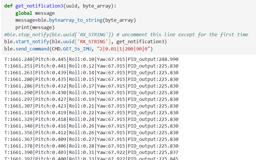
            ble.send_command(CMD.GET_5s_IMU, "2|0.01|1|200|90|0")
Here is a output example.

3. Lab Tasks
3.1 P/I/D discussion
From the above output, The sampling rate is about 100 hz. Following the lab5, I know the Kp should be equal to maximum pwm value/maximum error. Here the maximum error is 180 degree. Therefore Kp should be 255/180=1.42. The Kp is finally set to 2 to achieve a quick rotation. As Ki will multiplied by the integrated value, Ki should be equal to Kp/100 Hz=0.0142. The Ki is finally set to 0.01. Kd has a relatively small effect and the final value I set is still 1. Just like lab5, I close the integrator when the error is small.
3.2 Tips and tricks
As the rotation need a higher PWM value, the minimum value of PWM is set to 90. As it need different set point, I solve the derivative kick problem following the instructions in lab5. The low pass filter is implemented in lab2 so there is no need to implement a new one. Besides, the full-scake range of gyroscope is ±250/500/1000/2000 which is enough for this robot.
3.3 Implementation
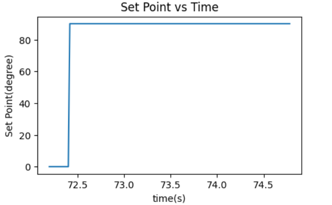
The first thing I need to implement is to add a PID controller so that the robot can always rotate to the set point (yaw=set point). Besides, I also change the set point from 0 to 90 after few seconds so the robot can rotate 90 degrees. Here is the core code.
            void PID_forimu(float Kp_imu,float Ki_imu,float Kd_imu,int Imax_imu,int minspeed_imu,float setPoint_imu){
          double error =  input_PID - setPoint_imu;

          // calculate the integral
          errSum += error;

          if(errSum>Imax_imu){
            errSum=Imax_imu;
          }
          if(errSum<(-Imax_imu)){
            errSum=-Imax_imu;
          }
          if(error<50){
             errSum=0;
          }

          // calculate the derivate consider the derivate kick
          double dErr = lastInput - input_PID;

          // get the output
          output_PID = Kp_imu * error + Ki_imu * errSum + Kd_imu * dErr;

          if(output_PID>3){
            output_PID+=minspeed_imu;
          }
          else if(output_PID<-3){
            output_PID-=minspeed_imu;
          }
          if(output_PID > 254){
            output_PID=254;
          }
           if(output_PID < -254){
            output_PID=-254;
          }


          // record the error and the time now
          lastErr = error;
          lastInput = input_PID;


        }
            input_PID = yaw;
            if(icnt>600){
              setPoint_imu=90;
              errSum=0;

            }
            PID_forimu(Kp_imu,Ki_imu,Kd_imu,Imax_imu,minspeed_imu,setPoint_imu);

            change_speed(output_PID,-output_PID);
The video is shown below. I also change the yaw several times and the robot always rotate back.
In order to show the situation when the set point changes, I use several graphs to show the relevant data. The graph of set point vs time is shown below.

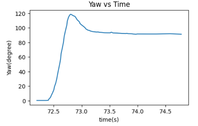
The graph of yaw vs time is shown below.

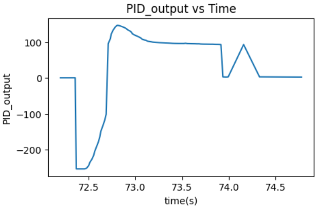
The graph of output_pid vs time is shown below.

3.4 (5000)Wind-up implementation and discussion
I also use the same wind-ip implementation in lab5. It works well as it can achieve the same goal no matter what the floor surface is.
Back to the main page