Lab 5: Linear PID control and Linear interpolation
1. Objective
The main purpose of this lab is to implement PID controller with suitable values. I will also explore extrapolation and some tips and tricks while using PID controller.
2. Prelab
In order to get the debugging data after executing PID controller and all other data, I need to integrate the code from previous labs and create a function which implements PID controller. Here is the code of a basic PID controller.
 void ComputePID(double Kp,double Ki,double Kd) {


     double error =  input_PID - setPoint;

    // calculate the integral
    errSum += error;


    // calculate the derivative
    double dErr = error - lastErr;

    // get the output
    output_PID = Kp * error + Ki * errSum + Kd * dErr;


    // record the error and the time now
    lastErr = error;

          }
I also create several arrays and use previous code to send back the data to computer. Here is part of the code. It will stop after 200 iterations.
 for(int i=0;i<200;i++){
              tx_estring_value.clear();
              tx_estring_value.append("T:");
              tx_estring_value.append(time_stamp1[i]/1000);
              tx_estring_value.append("|");
              tx_estring_value.append("TOF1:");
              tx_estring_value.append(distance1_array[i]);
              tx_estring_value.append("|");
              tx_estring_value.append("TOF2:");
              tx_estring_value.append(distance2_array[i]);
              tx_estring_value.append("|");
              tx_estring_value.append("PID_output:");
              tx_estring_value.append(output_pid[i]);
              tx_estring_value.append("|");
              tx_estring_value.append("Pitch:");
              tx_estring_value.append(pitch_array[i]);
              tx_estring_value.append("|");
              tx_estring_value.append("Roll:");
              tx_estring_value.append(roll_array[i]);
              tx_estring_value.append("|");
              tx_estring_value.append("Yaw:");
              tx_estring_value.append(yaw_array[i]);
              // write the appended string
              tx_characteristic_string.writeValue(tx_estring_value.c_str());

          }
          change_speed(0,0);
Here is the code in Python. It is quite similar to before except with a new command and three input values which are Kp,Ki,Kd.
            def get_notification3(uuid, byte_array):
            global message
            message=ble.bytearray_to_string(byte_array)
            print(message)

            ble.start_notify(ble.uuid['RX_STRING'], get_notification3)
            ble.send_command(CMD.MOVE_WITH_PID, "|0.1|0.02|0.001")
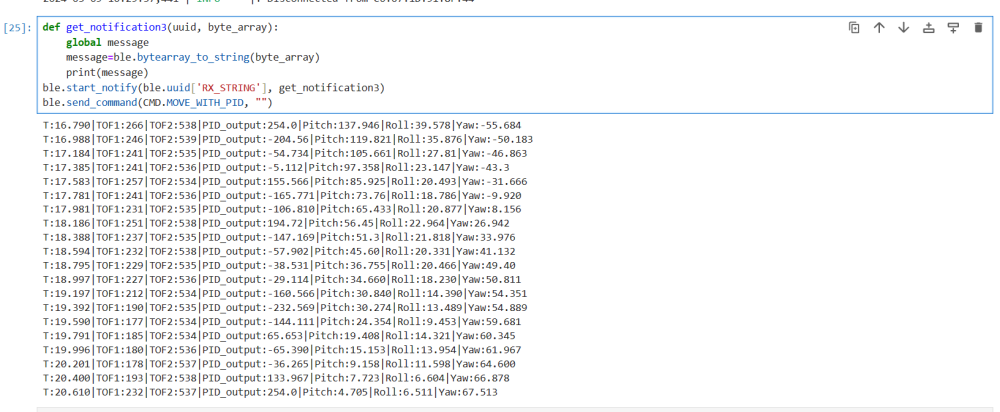
The result is like:

3. Lab Tasks
3.1 P/I/D discussion
From the previous image, it can be observed that the average sample period is about 200ms. Therefore, the sampling frequency is 5 Hz. It can be improved by extrapolation in the future. The range of TOF sensor is about 4m. Here, I put the robot 2000 mm away from the wall. In order to get the speed of the robot, I looked at one of the trials and calculate the result.

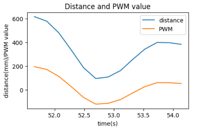
It can be observed that the maximum speed is 0.72m/s and the maximum PWM value is 255. The maximum error is 2000-304=1704 mm which is approximate to 1700 mm.
From the course, The Kp should be equal to maximum pwm value/maximum error which is 255/1700mm=0.15. The Kp is finally set to 0.06. As Ki will multiplied by the integrated value, Ki should be equal to Kp/5 Hz=0.03. The Ki is finally set to 0.01. Kd should be equal to maximum pwm/(maximum speed/ sampling time)=255/3.6=70. Kd has a relatively small effect and the final value I set is 1. The reason I set all these values smaller than it should be is because it can not stop in time due to the inertia. Therefore, I need to set these value smaller to get a smaller PWM value.
3.2 Working system
The deadband of this car is about 40 which is measured from lab 5. Therefore, the PWM should add 40 if it is not small enough. The wind up value I set is 200. If the value of integrator is larger than 200, it will be equal to 200. As the set point is fixed, there is no need to worry derivative kick. The error change is quite slow so there is no need to add a low pass filter.Besides, the PWM value should not exceed the maximum limit (255) and the initial error should be 1700. Here is the code.
        void ComputePID(double Kp,double Ki,double Kd,int Imax,int minspeed) {


        double error =  input_PID - setPoint;

        // calculate the integral
        errSum += error;

        if(errSum>Imax){
        errSum=Imax;
        }
        if(errSum<-Imax){
            errSum=-Imax;
        }
        // calculate the derivate
        double dErr = error - lastErr;

        // get the output
        output_PID = Kp * error + Ki * errSum + Kd * dErr;
        if(output_PID>1){
            output_PID=output_PID+minspeed;
        }
        if(output_PID<-1){
            output_PID=output_PID-minspeed;
        }
        if(output_PID >= 255){
            output_PID=254;
        }
        if(output_PID <= -255){
            output_PID=-254;
        }


        // record the error and the time now
        lastErr = error;

}
3.3 Extrapolation
Follow the instructions, I directly implement the extrapolation with last two data points. Here is the code.
         current_time = (int)millis();
        if (distanceSensor1.checkForDataReady())
        {


        distance1 = distanceSensor1.getDistance(); //Get the result of the measurement from the sensor

        //Extrapolation
        last2_distance = last1_distance;
        last1_distance = distance1;
        last2_time = last1_time;
        last1_time = current_time;
        distanceSensor1.clearInterrupt();

        }
        else
        {
            if(last2_distance!=0&&last2_time!=0)    //check if it just begin
            {
                distance1 = last1_distance - (last2_distance-last1_distance)*(current_time-last1_time)/(last1_time-last2_time);
            }

        }

        if(distance1<0){
            distance1=0;
        }
        // get and process the output of pid
        input_PID=distance1;
        ComputePID(Kp,Ki,Kd,Imax,minspeed);
        change_speed(output_PID,output_PID);
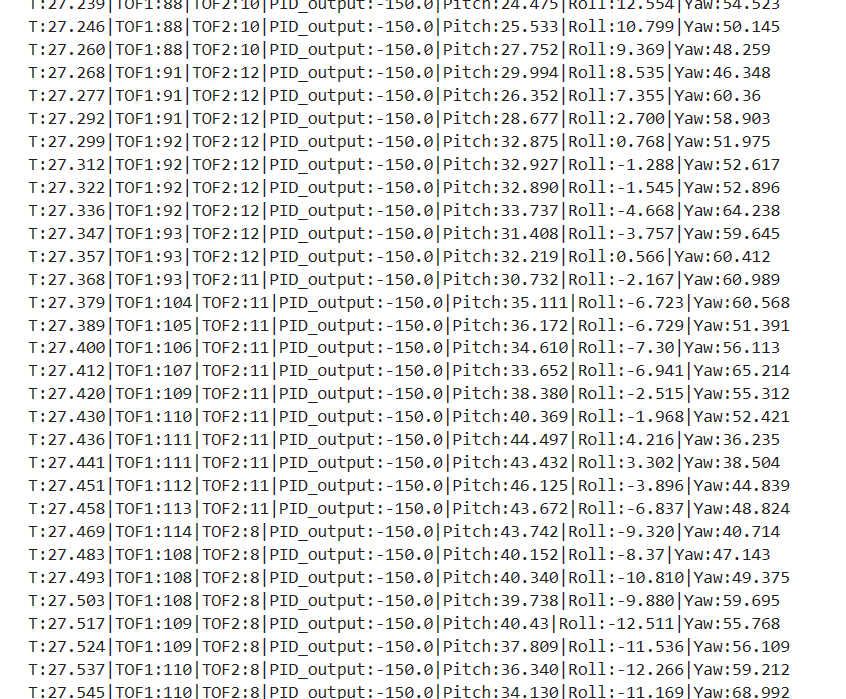
The result is shown below.

It can be observed from the image that the rate of PID control loop is about 1/10ms=100Hz which is much faster than the rate of two TOF sensors' update.
3.4 videos
Here are three videos. The distance of first one is not enough while the other two shows how the final version of the linear PID controller control this robot.
video 1
video 2
video 3
3.5 (5000)Wind-up implementation and discussion
I have applied the wind-up protection for my integrator. Besides, I also let the Ki to be equal to 0 when the car is close to the wall. The integrator sometimes creates very strange situation. The robot may move backward without stopping or crash to the wall. Here is the video. I believe it is because the delay produced by the integrator.