Lab 4: Motors and Open Loop Control
1. Prelab
1.1 Diagram of connections
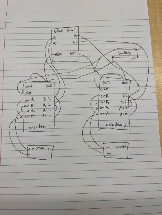
The first thing I focus is the PWM pins used on the Artemis board. I choose pins 2,5,11,12 as they are available for this task and won't affect other functions. They connect to two input pins on each motor drivers. On the other hand, the 4 output pins need to connect the motor's input and output. Therefore, the input pins and output pins need to be soldered together. The battery need to connect to motor drivers' VIN and GND, so I use two wires to connect to the positive pole and another two to connect to the negative pole. The other end of these wires connect to two motor drivers' VIN and GND. Besides, the two GND pins on the motor driver need to connect two GND pins on the Artemis board. Here is the diagram which shows the connection in detail.
1.2 Battery discussion
The reason of powering Artemis board and the motor drivers from different batteries is that they have different voltage requirement and this can avoid some interference produced by motors.
2. Lab Tasks
2.1 Setup with power supply and oscilloscope hookup
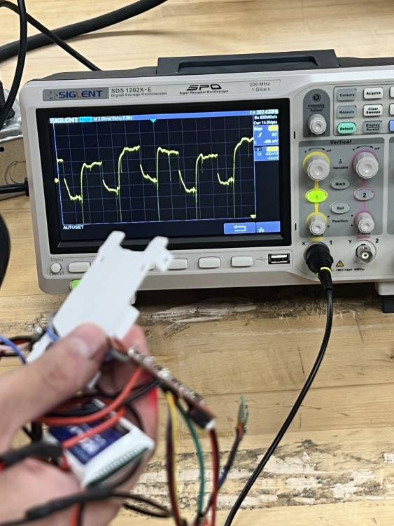
I first keep the motor driver powered and use PWM signal to control the power on the output of motor driver. Here is a picture of oscilloscope. The voltage is actually not that stable due to some noise. Besides, I also believe that my motor driver may have some problems but I can not fix it after several tests.
2.2 Power supply and analogWrite code for testing motor drivers
I use the 3.7V, 850mAh battery and find it enough to power both motors. Here is the code of analogWrite which can let the car to move straight

2.3 Video of both wheels spinning
Set the PWM value to 130, both wheels are spinning in a high speed.
2.4 Picture of all the components secured in the car
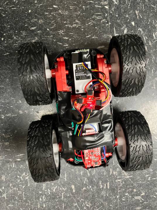
In the beginning, I tried to put all components in their designed place but one of my motor driver was broken so I have to redo all the things. Due to my poor soldering skills, it will lead to short circuit sometimes if keep everything tight together. Therefore, I use capacitor tape to fix everything. two motor drivers and a battery are below the Artemis board and other things can be observed in the picture below. Here is the picture
2.5 Lower limit PWM value discussion
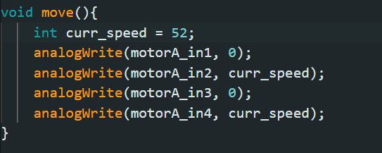
I tested several PWM values and find out 52 is the lowest value that can let the robot beats static friction and moves forward. Here is the code and the video I record.
2.6 Calibration demonstration
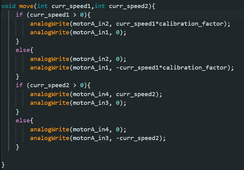
In order to let the robot move straight, I set a calibration factor which is equal to 1.2 and use it to time the PWM value on one side. I also modify my move function so the wheels can spin forward and backward. Here is the code and the video. It shows that the robot can follow a straight line for about 2 meters.
2.7 Open loop code and video
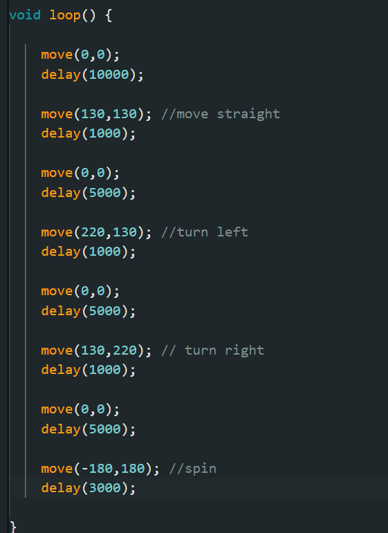
In the open loop control stunt, I let the robot to move straight for 1 second. Then, it will turn left and turn right. In the end, It spins 3 second. There is a 5 second interval between each action. Here is the code and video. The calibration factor need to be fine tuned in the future and the performance of motor can be affected by the battery level.
(5000) 2.8 AnalogWrite frequency discussion
In 2.1, the picture shows the frequency of PWM on the top right corner which is 202.42Hz. It is faster than ToF sensor so it is adequate for motors to take action based on the environment changes. If we generate faster PWM signal, it can react more quickly in some extreme situations.

(5000) 2.9 Lowest PWM value speed discussion
One motor's lowest PWM value to overcome the dynamic friction and keep it running is 40. The other one has a higher value which is 50. Therefore, the lowest PWM value to keep it running is 50. Here is a video.