.png)
The main goal of this lab is to use and test the IMU ICM 20948. It also contains recording the stunt of the RC car.
First, I connect the IMU to the Artemis board and install the SparkFun 9 DOF IMU Breakout. Here is a picture of the connection.
.png)
After running the example, It returns the IMU data. It can be seen in the following video.
In the datasheet, it shows that the AD0_VAL is used to change the I2c address of IMU.
When I flip, rotate and accelerate the board, the data of accelerometer and gyroscope changes rapidly.
I add a function of blinking the LED and use the for loop to run it three times. It now blinks three times in the beginning, watch it below.
Using the surface and edges of my table, I try to do 90 degree tilt and roll. Here is the result.
Here is a picture of the code
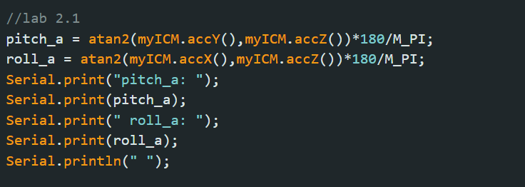
According to the data from the above part, The measured pitch range is [-90.82, 91.51] and the measured roll range is [-92.02, 93.26]. The conversion factor is
\( Pitch Conversion Factor = \frac{90-(-90)}{91.51-(-90.82)} = 0.98 \)
\( Roll Conversion Factor = \frac{90-(-90)}{93.26-(-92.02)} = 0.97 \)
The final pitch and roll degree can be calculated by the equation:
\( Final pitch output = -90 + Conversion Factor (measured output- (-90.82))\)
\( Final roll output = -90 + Conversion Factor (measured output- (-92.02))\)
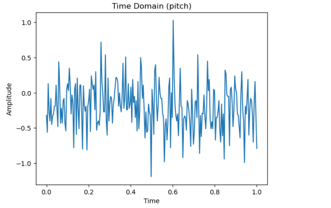
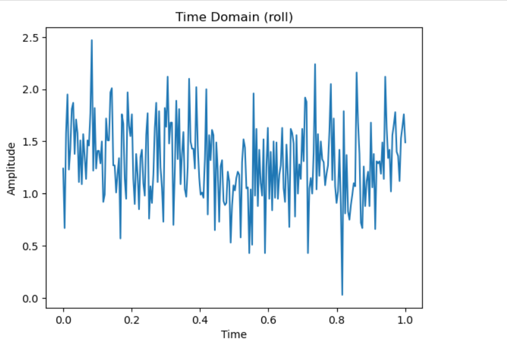
After I record the data and load the data in python, I first plot the pitch and roll angle in time domain with sample rate equals to 240 Hz. The first picture is the pitch angle in time domain and the second one is the roll angle in time domain.
After fourier transform, the pitch and roll angle in frequency spectrum is:
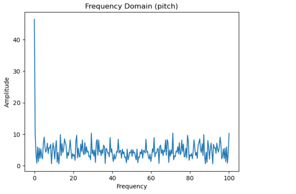
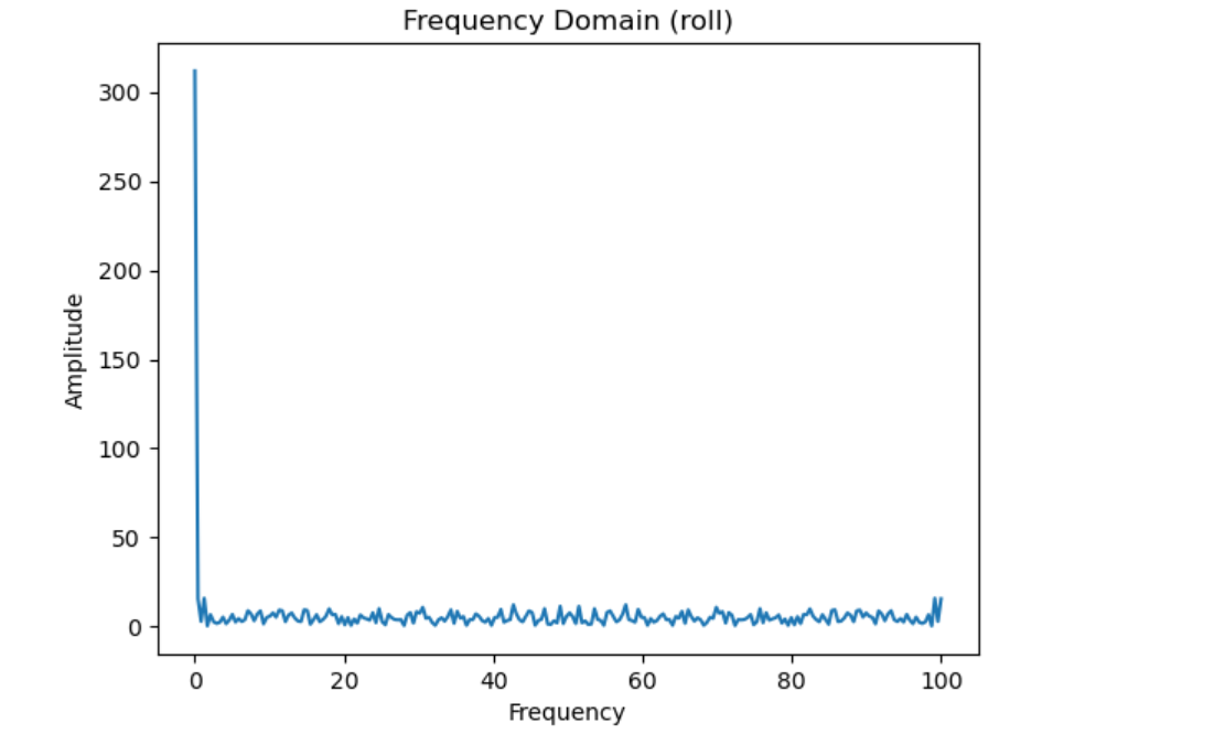
In the datasheet, it shows that the IMU already has a low pass filter so it has little noise in frequency spectrum. The cut off frequency I select is 20 Hz. With the equations:
\( a=\frac{T}{T+RC} \)
\( fc=\frac{1}{2RC\pi} \)
\( T=\frac{1}{f} \)
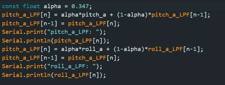
Here fc is the cut off frequency and f is the sample rate, and the a is equal to 0.347. However, the low pass filter can not change the result too much. Here is the code:
Use the code below, I change the IMU positions and it returns different pitch, row and yaw.
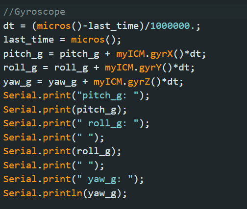
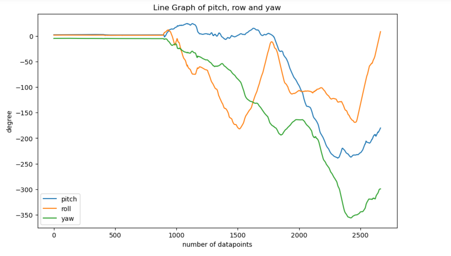
Compared to the data in accelerometer, the gyroscope data increases rapidly as time goes on. Besides, the sample rate need to be high, as low sample rate will cause the updated data become slower.
Use the equation learned in the class, the code of complementary filter is shown below.

Then, I tilt and roll the IMU to different degrees. The video shows that the result is quite accurate
Using the equations in the class, the program returns pitch, roll and yaw. I delete all delay and serial print. The sample rate is about 64 Hz. That is because the data rate of magnetometer is much more smaller than others. Moreover, the main loop on the Artemis board runs faster than the IMU process new values as it's execution time is only about 3ms
In arduino, I write a new method which can calculate pitch,roll,yaw and timestamp in float numbers. The data is stored in arrays. It is used in a new case which is called "GET_5s_IMU". Then, each pieces of data is sent in a for loop. The code is shown below.
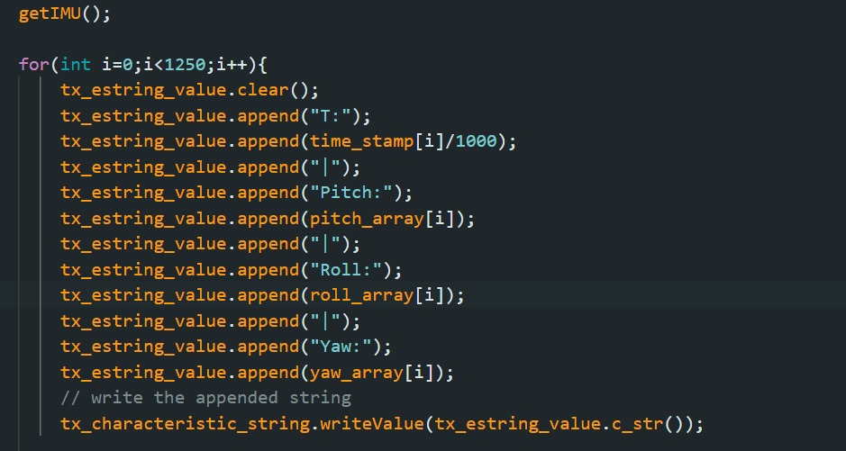
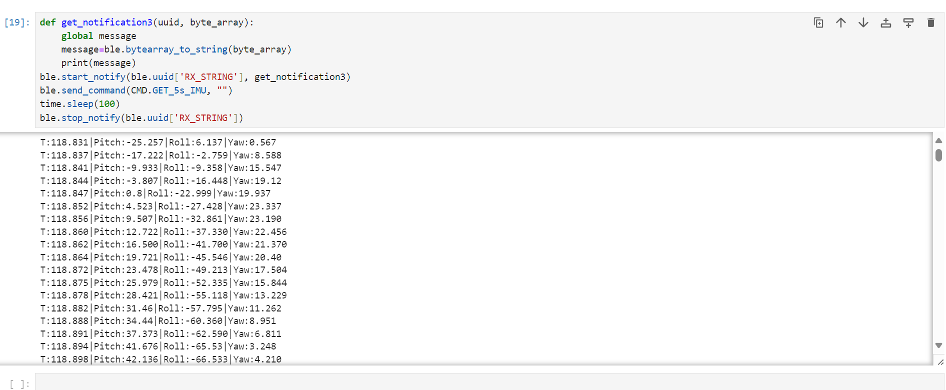
As the Artemis board has 384kB of RAM and each piece of data is 8 bytes (4 float numbers:pitch,roll,yaw,timestamp), it can store 48000 pieces of data. The timestamp shows the interval of each piece of data is about 4ms. Therefore, in order to get 5s IMU data, the Artemis board need to store and send 1250 datapoints. Here is part of the result in jupyter lab.
Here is the video of the toy car.