The main goal of this lab is to set up the Arduino IDE and Artemis board. The lab also includes using the board LED, reading and writing serial messages, using the temperature sensor and Pulse Density Microphone. Besides, it also contains a small programming task.
First, I need to install Arduino IDE. The Arduino IDE can be downloaded here
I hooked the Artemis board up to my computer and followed the setup instructions to install the Arduino Core for Apollo3. After that, I click "Tools" -> "Board" -> "SparkFun Apollo3 Boards" and choose "Redboard Artemis Nano". Then, I click "Tools" -> "Port" and choose "COM3" to select the port. In the end, I chose 115200 baud in the Serial Monitor to make sure it returns correct message.
I click "File" -> "Examples" -> "01.Basics" -> "Blink" to load the blink example and click "upload" button to run the example. The blink on the Artemis board can be seen in the following video
After running the Serial example, you can view the output and provide input through the serial monitor. The output is same as the input.This can be seen in the following video.
After running the analog read example, I touch the the Artemis board for a while. It can be observed from the following video that the variable "temp(counts)" increase from about 33000 to about 33600. Therefore, the temperature sensor works well.
First, I ran the PDM example. While it is running, I first make some noise to change the highest frequency and then use my mobile phone to produce a steady sound which is 2117 Hz. It can be observed from the following video that the highest frequency keeps unchanged for a few seconds
In order to achieve the function described in the instruction, I use the variable "ui32LoudestFrequency" in 3.5 to get the highest frequency first. If it is similar to 440 Hz (musical "A" note), turn on on the LED (that is "digitalWrite(LED_BUILTIN, HIGH)") and turn off otherwise. The code and the situation of LED are shown in the following video.
From this part, I learnt how to set up the Artemis board and how to program my board. I also test the sensor,microphone and LED of the Artemis board.
The part 2 focuses on the communication between the computer and the Artemis board using the Bluetooth stack. I will use Python and Arduino programming language to build a framework for sending and receiving data through bluetooth.
As I have installed Python before, the first thing I need to do is to install venv. After using "python3 -m pip install --user virtualenv" to install, I navigated it to my project directory and created a new virtual environment which is called "FastRobots_ble". Then, I used ".\FastRobots_ble\Scripts\activate" and installed numpy,pyyaml,colorama,nest_asyncio,bleak,jupyterlab In the end, I installed ArduinoBLE from the library manager and upload ble_arduino.ino which is from here The MAC address is now printed.Here is an image

After I downloaded and copy the directory into my project directory, I activated my virtual environment and start the jupyter server. I read through the codebase and I understand the demo.ipynb mainly handle various BLE operations. It can write in some data and also receive the data from the Artemis board.
First, I replace the artemis_address value with the MAC address in connections.yaml. Then, I change the BLEService UUID by generating a new UUID and replacing the BLEService UUID in ble_arduino with it. In the end, I ran all the cells in demo.ipynb to use and test BLE.
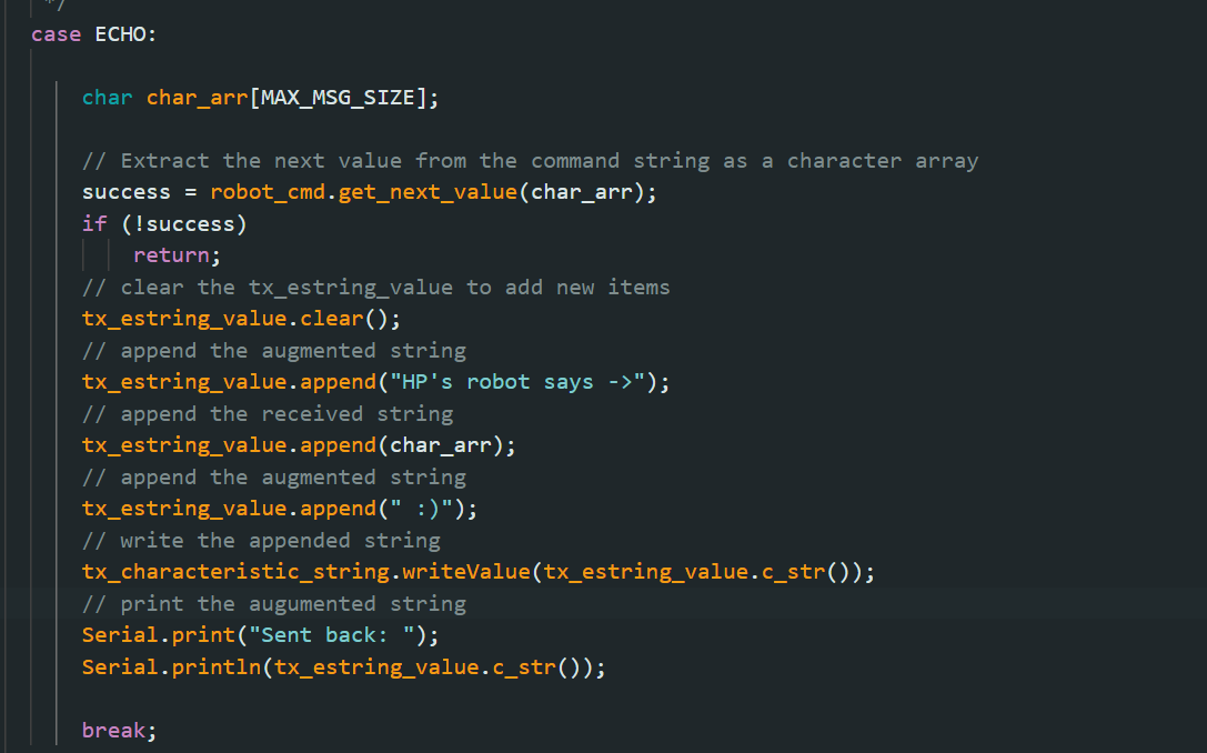
In the "case ECHO" of ble_arduino.ino, I wrote the appended string into "tx_estring_value" and it will then write to the characteristic which is called "tx_characteristic_string". The computer first send ECHO command and then receive the string from RX_STRING. Here are the result and the code I wrote in arduino and jupyter lab.


In order to add a new command, I need to first add the command in "enum CommandTypes" of ble_arduino.ino. Then, I need to add it in cmd_types.py and restart the kernel. The code is quite similar to the previous one. The only thing I need to change is to use "millis()" to get the number of milliseconds since the program starts. I also used "(float)" to avoid overflow and get a more accurate number when it needs further process. Here are the result and the code I wrote in arduino and jupyter lab.
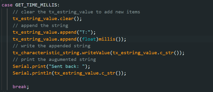


I use the "start_notify()" in the class ArtemisBLEController to set up a notification handler. Once the computer send the GET_TIME_MILLIS command, the Artemis board will return the string value. Then, I print the data I received out. Here is the result and python code.

First, I put the code of GET_TIME_MILLIS into a for loop. In jupyter lab, I start notify and then send the command. Then, it will sleep 1 second and stop notify. Here is the result and the code of jupyter lab and Arduino.
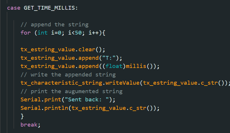
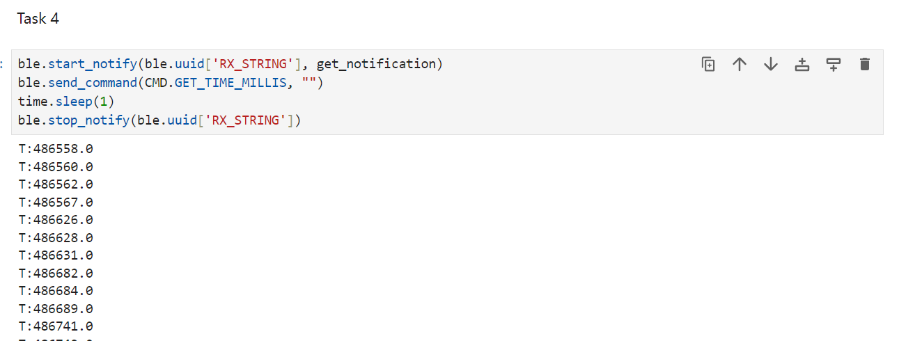
Each message contains "T:" and a float number, so each message has 6 bytes. The interval between each message is about 3 milliseconds. Therefore, the data transfer rate is 2 byte/millisecond= 16Kbps
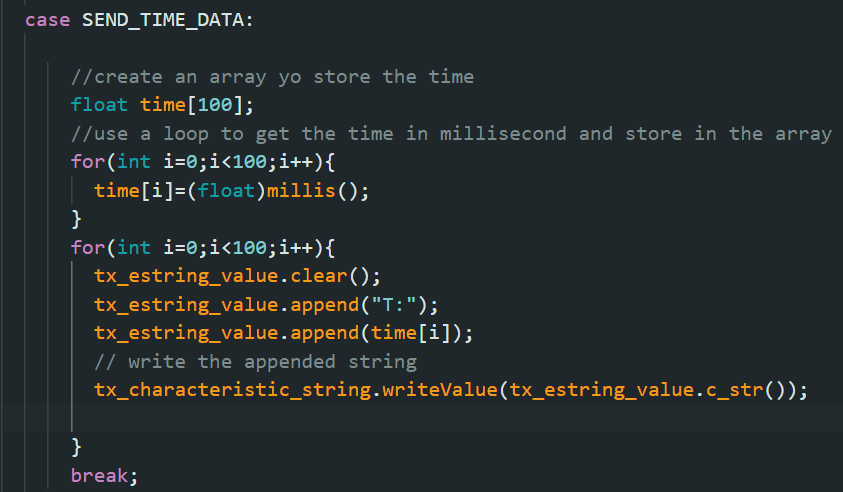
First, I add a new command which is called SEND_TIME_DATA. I also create an array and it uses "millis()" to get the time via a loop. Then, the Artemis board send each data points with another loop. In jupyter lab, I create a list in python which is called "data_points1" to store the received data. Here are the result and the code I wrote in arduino and jupyter lab.

Using similar way. I add a new command GET_TEMP_READINGS and use another array to store the value produced by "getTempDegF()". Then, the Atemis board send the data and I use another list to store the data points. Here are the result and the code I wrote in arduino and jupyter lab.
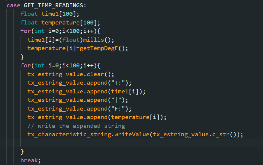
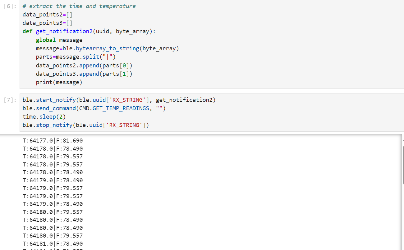
The first method read and send the data at same time while the second method first read the data into array and then send each data points. The advantage of the first method is that it is a synchronized way to get the data but the data transfer rate is slow due to bottleneck of sending data. The second method is a asynchronized method but the data transfer rate is about 1.4Mbps which is much faster than the first method. If the data is 6 byte, the 384 kB Artemis board can store 64000 pieces of data.
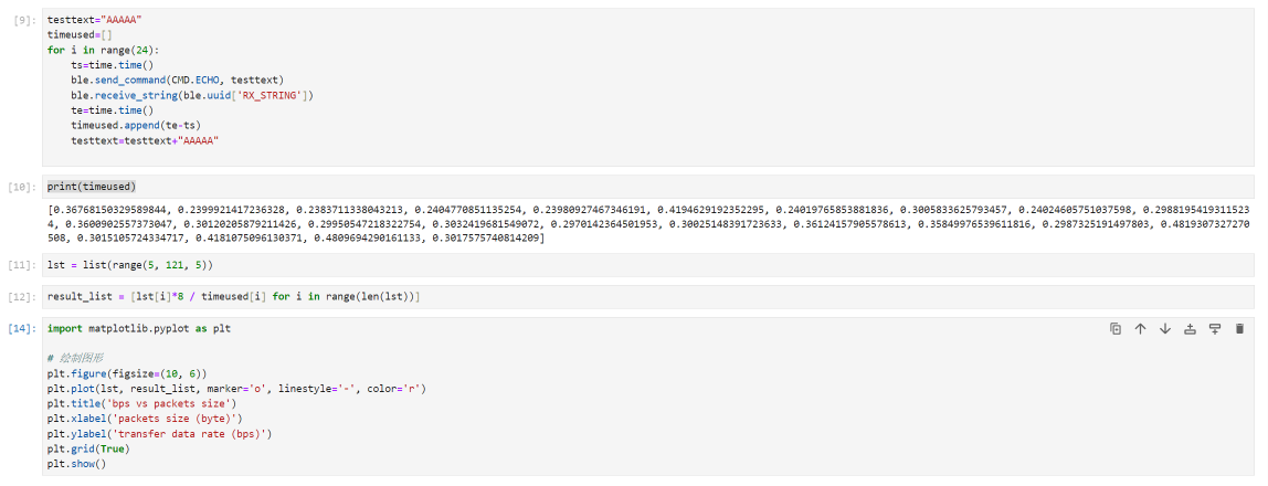
In order to test the effective data rate, I reuse the ECHO commandand let it send back the input data from the computer. In the beginning, I send and receive 5-byte data and then add 5 more byte to send and receive each times. Finally, I send and receive 120 bytes. Then, I calculate the bps each times and here is a plot made by python.
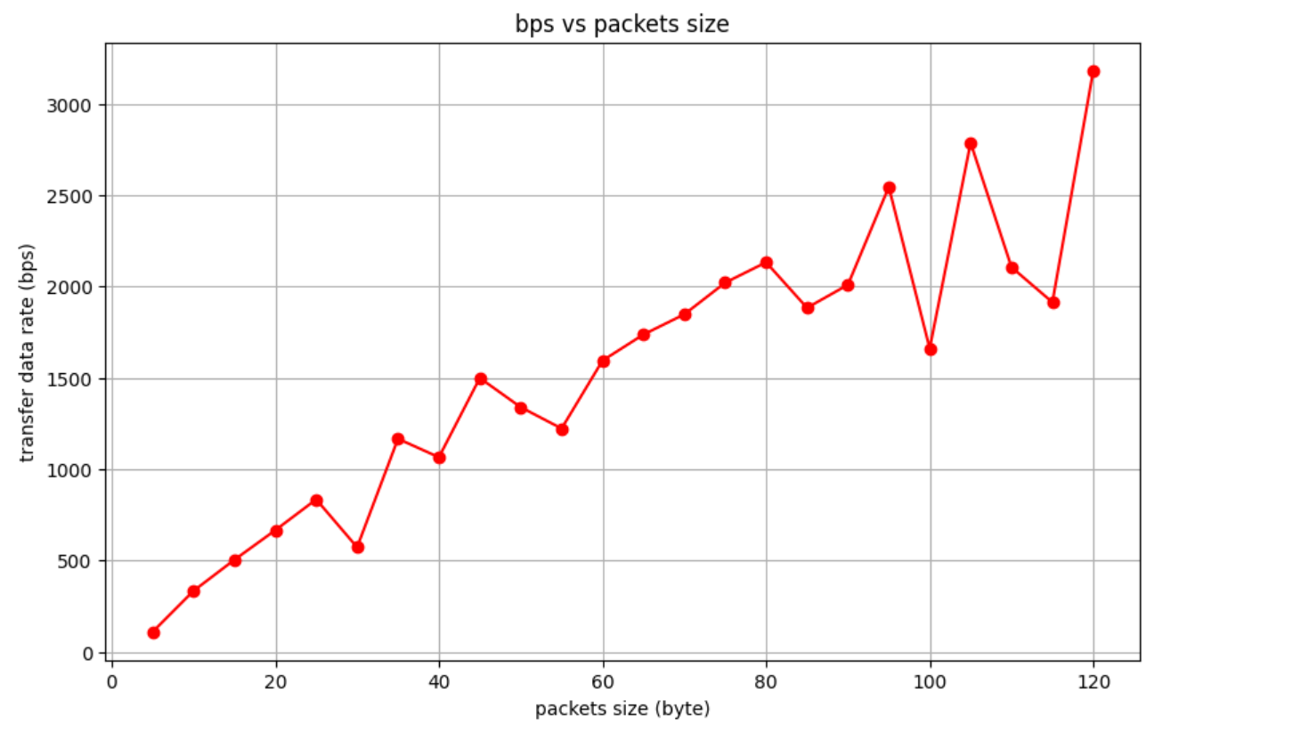
It can be observed that the short packets introduce some overhead as the effective data rate is low. Although, the performance of large packets are not stable, but they do help to reduce overhead. The code in python is shown below.
When I send the data at a high rate from the Artemis board to my computer, I labeled each data points and found a few packages are missing. Therefore, the computer did not read all the data published from the Artemis board.
In this part, I learned how to write code in python and arduino language to implement some functions. The main challenge is to understand the difference between two data sending ways. I also understand the overhead of different packet sizes.
Back to the main page